HONAREL


Product Details

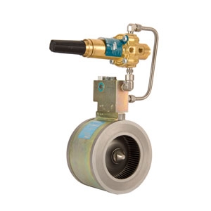
  1. Composition of axial flow valve
    The axial flow valve is composed of three parts: 1) valve body; 2) control manifold; 3) actuator.
    The valve body consists of four components: 1) two interchangeable rectifying fence sealers (stainless steel); 2) valve body (galvanized carbon steel); 3) expandable modified rubber sleeve.
    Different materials of the sleeve can be selected to meet various requirements of working temperature, wear resistance, and expansion, and special material sleeves can be provided according to customer needs to adapt to low temperature and corrosive applications. The main materials of the sleeve include: 1) Hydrin (H), 2) Buna (B), 3) Viton (V), 4) Natural rubber (N), 5) Fluorosilicone (F).
    The entire valve is tightened by a bolt and rounded cap screw, and the central closure depends on the O-ring under the rounded cap screw to seal. The upstream and downstream rectifying fence passage are sealed on the valve body by the roller pin O-ring, and the roller pin aligns the rectifying fence sealers with the valve body.
  2. Working principle of axial flow valve
    · Throttling position
    Fully open position
    · Closed position
    When the control pressure is low and the downstream pressure exceeds the load and forces the valve to fully open, the downstream rectifying fence completely protrudes into the upstream section of the axial flow valve and the sleeve inside the rectifying fence. When the sleeve continues to expand and expand, it adheres to the inside of the axial flow valve. The control pressure enters the outside of the sleeve, and due to the expansion of the sleeve, part of the downstream rectifying fence is exposed, and the airflow begins to pass through the downstream exhaust port. The diameter is slightly smaller than the rectifying fence, and when the downstream pressure and control pressure are exceeded. When the downstream gas is sufficient and the remaining pressure reaches equilibrium, the sleeve will close the valve. The sleeve forces the inner and outer surfaces to maintain a balanced state.
  3. Control Manifold
    The combination manifold includes an integral adjustable restrictor to adjust the response speed of the axial flow valve, and a filter located at the front end of the restrictor and actuator to remove foreign matter. A single combination manifold can be used with all axial flow valves ranging from 2″ to 12″.
    When the pressure difference before and after the axial flow valve is relatively small, a Venturi-type manifold can be used. This manifold contains a specially designed nozzle that reduces the pressure differential required for full valve opening while maintaining control sensitivity and accuracy of control pressure, thereby extending the versatility of the axial flow valve. The same manifold can be used with all sizes of axial flow valves.
  4. Axial Flow Valve Ring Slightly Open (Kgf/lcm²) Fully Open (Kgf/lcm²) Maximum Allowable Differential Pressure (Kgf/lcm²)
    Comb-Type Manifold Venturi Manifold Comb-Type Manifold
    Model: AFV-300 5L* 0.1 0.04 0.35
    Model: AFV-300 5 0.25 0.1 0.5
    Model: AFV-300 7 2 0.4 2
    Model: AFV-600 7 2 0.8 2

    *Note: The 5L ring is only applicable to axial flow valves with DN50, 80, 100, 150, 200.

    Key:

    • Slightly Open (Comb-Type Manifold) = pressure differential when the valve is slightly open using a comb-type manifold.
    • Fully Open (Comb-Type Manifold) = pressure differential when the valve is fully open using a comb-type manifold.
    • Slightly Open (Venturi Manifold) = pressure differential when the valve is slightly open using a Venturi manifold.
    • Fully Open (Venturi Manifold) = pressure differential when the valve is fully open using a Venturi manifold.
    • Continuous = maximum allowable differential pressure for continuous operation.
    • Intermittent = maximum allowable differential pressure for intermittent operation.

Send Us A Message